ultraSURFACE – Achievements

Multi-Beam Optics

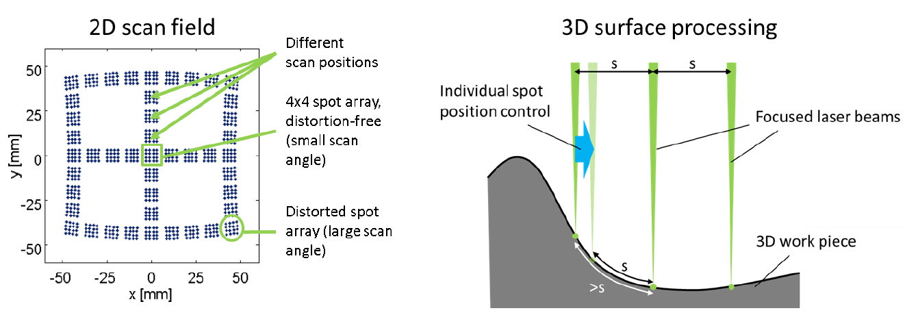
The use of multi-beam optics is already state of the art for laser structuring to increase the throughput of the process. But due to the high demands on the position accuracy of each spot (usually within single digit micrometres), these processes are limited to flat and non-tilted surfaces as well to very small scanning angles from the laser scanner. Curved or tilted surfaces and large scanning angles distort the spot array (cf. Figure 1) and the required position accuracy of spots on the work piece is not achievable anymore. Therefore, a spot position control unit is designed and realized within ultraSURFACE to allow the manipulation of the x-, y- and z position of the individual beam foci on the work piece.


Figure 1: left: Simulation of different scan positions for a 4x4 spot array. 2-dimensional deflection leads to distortion of the spot array. Right: processing of 3-dimensional surfaces requires individual position control of all spots.
© Fraunhofer ILT, Aachen, Germany.
Figure 1: left: Simulation of different scan positions for a 4x4 spot array. 2-dimensional deflection leads to distortion of the spot array. Right: processing of 3-dimensional surfaces requires individual position control of all spots.

Figure 2 shows the concept for the multi-beam optics: A diffractive optical element (DOE) splits the incoming laser beam into several beams. The beams are identical in size and power and only differ in their angle relative to the incoming beam. A telecentric relay optics focuses the beam into an intermediate focus some distance behind the relay optics. Due to the telecentricity of the relay module, the central rays of the beams propagate parallel to each other behind the relay. A mask may be placed behind the relay to block unwanted diffraction orders but is not required as the DOE can be designed in such a way that only desired diffraction orders are created. A spot position control unit, placed in front of/behind/around the intermediate focus allows to vary the lateral position (x,y) of each beam and to defocus each beam. A change in x- and/or y-position of the beam after the spot position control unit directly corresponds to a change in x- and/or y-position on the work piece. The ratio between the position changes depends on the ratio of the focal lengths of the relay optics and the focusing lens. Furthermore, defocussing will move the focal plane of the beam relative to the focal plane of the focusing optics. Thus, the focus position of each beam can be controlled in x-, y- and z-direction. A second relay optics images the DOE into the entrance aperture of the laser scanner. An F-Theta lens behind the scanner focuses the beams onto the work piece.

Figure 2: Concept for the multi-beam optics.
© Fraunhofer ILT, Aachen, Germany.
Figure 2: Concept for the multi-beam optics.

Design of the relay lenses

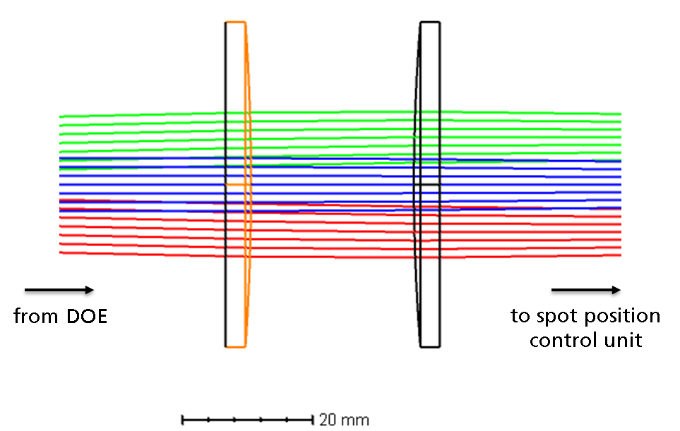
Figure 3: Design for the relay lenses. The relay is telecentric, i.e. the chief rays of each beam are parallel to the optical axis between the relay modules. Only commercially available standard lenses are used for this design. Note that the two shown lenses are not identical. The second relay is identical to the first relay but with inversed orientation.
© Fraunhofer ILT, Aachen, Germany.
Figure 3: Design for the relay lenses. The relay is telecentric, i.e. the chief rays of each beam are parallel to the optical axis between the relay modules. Only commercially available standard lenses are used for this design. Note that the two shown lenses are not identical. The second relay is identical to the first relay but with inversed orientation.

According to the application requirements, the multi-beam optics should create a 2x2 beam array with a beam separation of 5 mm on the work piece. Relays for multi-beam optics usually have high demands regarding a minimal distortion of the relay to achieve constant beam separations between the relay optics. However, for a square 2x2 beam array, distortion influences all beams equally and is therefore not a critical aberration. This allows for a two lens design based on commercially available standard lenses (cf. Figure 3). 

Spot Position Control Unit

The demands for the spot position control unit stem from the process (i.e. what kind of curvature or surface tilt needs to be compensated) as well as the optical design of the remaining multi-beam optics (e.g. distortion of the beam array for large scanning angles). With the chosen setup, each beam can deviate up to ±380 µm laterally from its target position and focus shifts of up to ±1 mm are required to keep the focus of each beam on the work piece for tilted surfaces (cf. Figure 1). Note that the required compensation for each individual beam is different so a global compensation is not possible.

Focus shifters

Focus shifters are part of most laser scanners and usually consist of two lenses where one lens is fixed and the other can be moved along the optical axis. The shift of the lens introduces defocus to the beam, moving the focal plane behind the f-theta lens further away from or closer to the lens. The challenge for the spot position control unit within ultraSURFACE is that each beam needs its own focus shifter without interfering with the other beams (cf. Figure 4). Therefore a miniaturised solution must be found that is small enough to avoid interference with other focus shifters or the other beams (e.g. blocking them out). While in principle the beam distance between the relay optics is a free parameter, the goal is to keep it as small as possible.


Figure 4: Concept for a miniaturized focus shifter with two lenses for each beam. One lens is movable to introduce the required focus shift between the relay lenses and after the F-Theta lens.
© Fraunhofer ILT, Aachen, Germany.
Figure 4: Concept for a miniaturized focus shifter with two lenses for each beam. One lens is movable to introduce the required focus shift between the relay lenses and after the F-Theta lens.

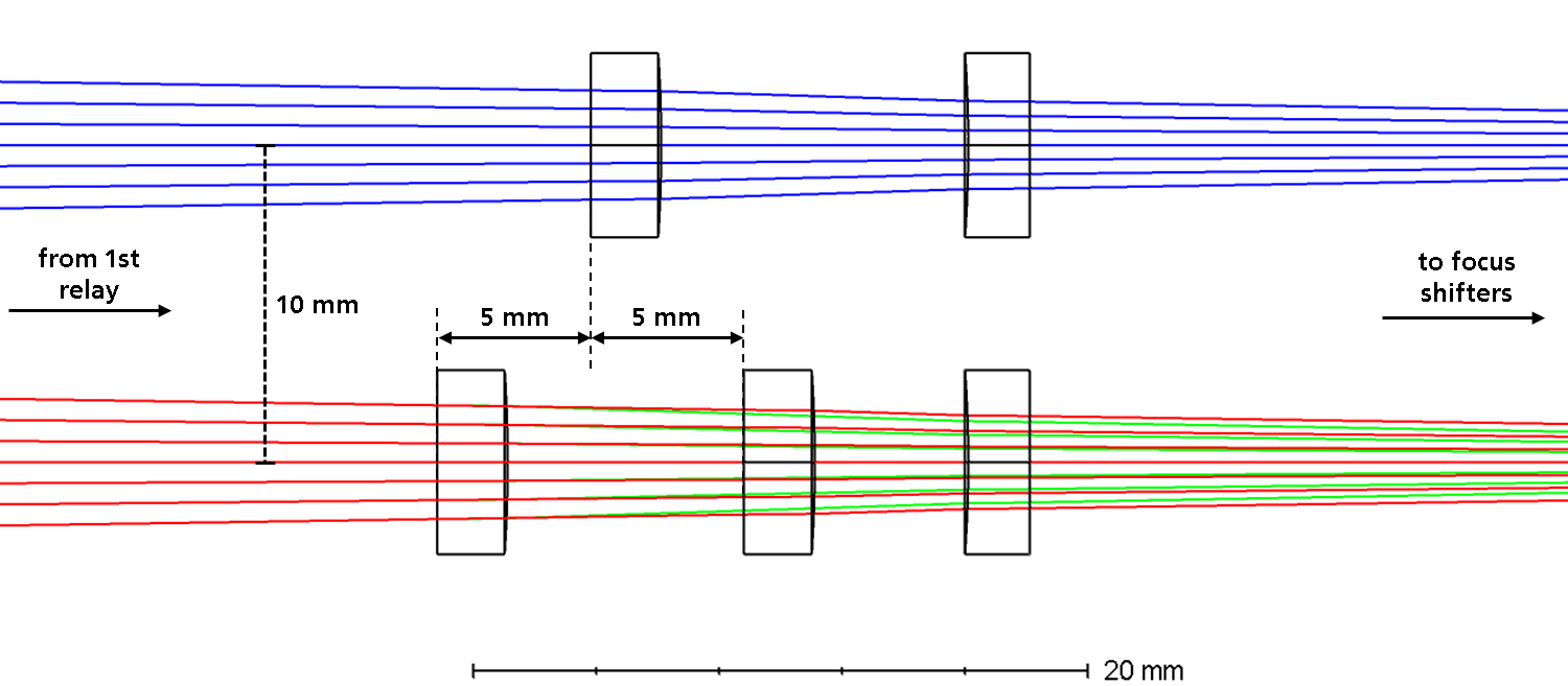
The optical design of the focus shifter is shown in Figure 5.  Each focus shifter consists of two commercially available lenses grinded down to an outer diameter of 6 mm. By moving the first lens ±5 mm along the optical axis of the beam, a total focus shift of 7.2 mm or a symmetrical shift of ±3.6 mm can be achieved for each individual beam

Figure 5: Optical design of miniaturized focus shifters. In the upper beam path, the first lens is in its “zero”-position. The lower beam paths show the first lens in the +5 mm (red beam path) and -5 mm (green beam path) position.
© Fraunhofer ILT, Aachen, Germany.
Figure 5: Optical design of miniaturized focus shifters. In the upper beam path, the first lens is in its “zero”-position. The lower beam paths show the first lens in the +5 mm (red beam path) and -5 mm (green beam path) position.

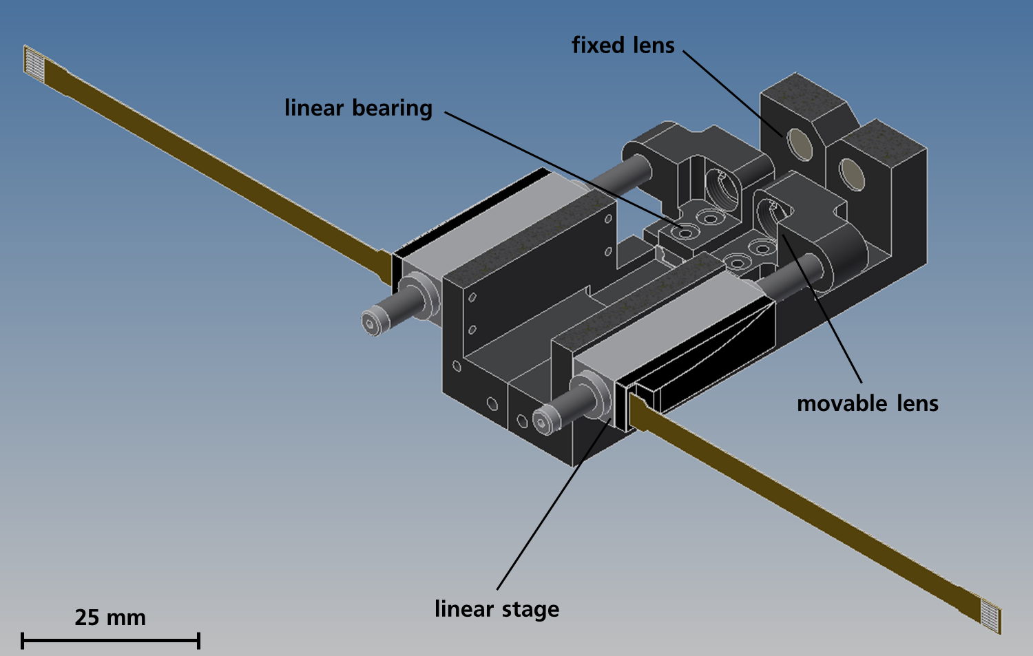
The mechanical design of the focus shifter is shown in Figure 6. Commercially available, high dynamic linear stages are used to move the first lens in the desired position while the second lens is held in place.

Figure 6: Half-section view of the focus shifters. The movable lenses are positioned via miniaturized, high dynamic linear stages.
© Fraunhofer ILT, Aachen, Germany.
Figure 6: Half-section view of the focus shifters. The movable lenses are positioned via miniaturized, high dynamic linear stages.
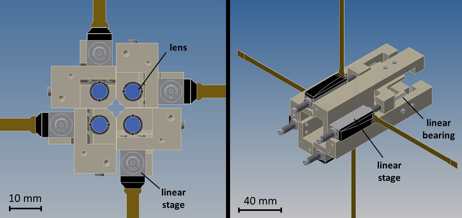
Figure 7: Frontal and isometric view of the updated focus shifters design. The new star shaped arrangement of the linear stages increases the distance between the stages and heavily reduces the interference of the stages with each other.
© Fraunhofer ILT, Aachen, Germany.
Figure 7: Frontal and isometric view of the updated focus shifters design. The new star shaped arrangement of the linear stages increases the distance between the stages and heavily reduces the interference of the stages with each other.

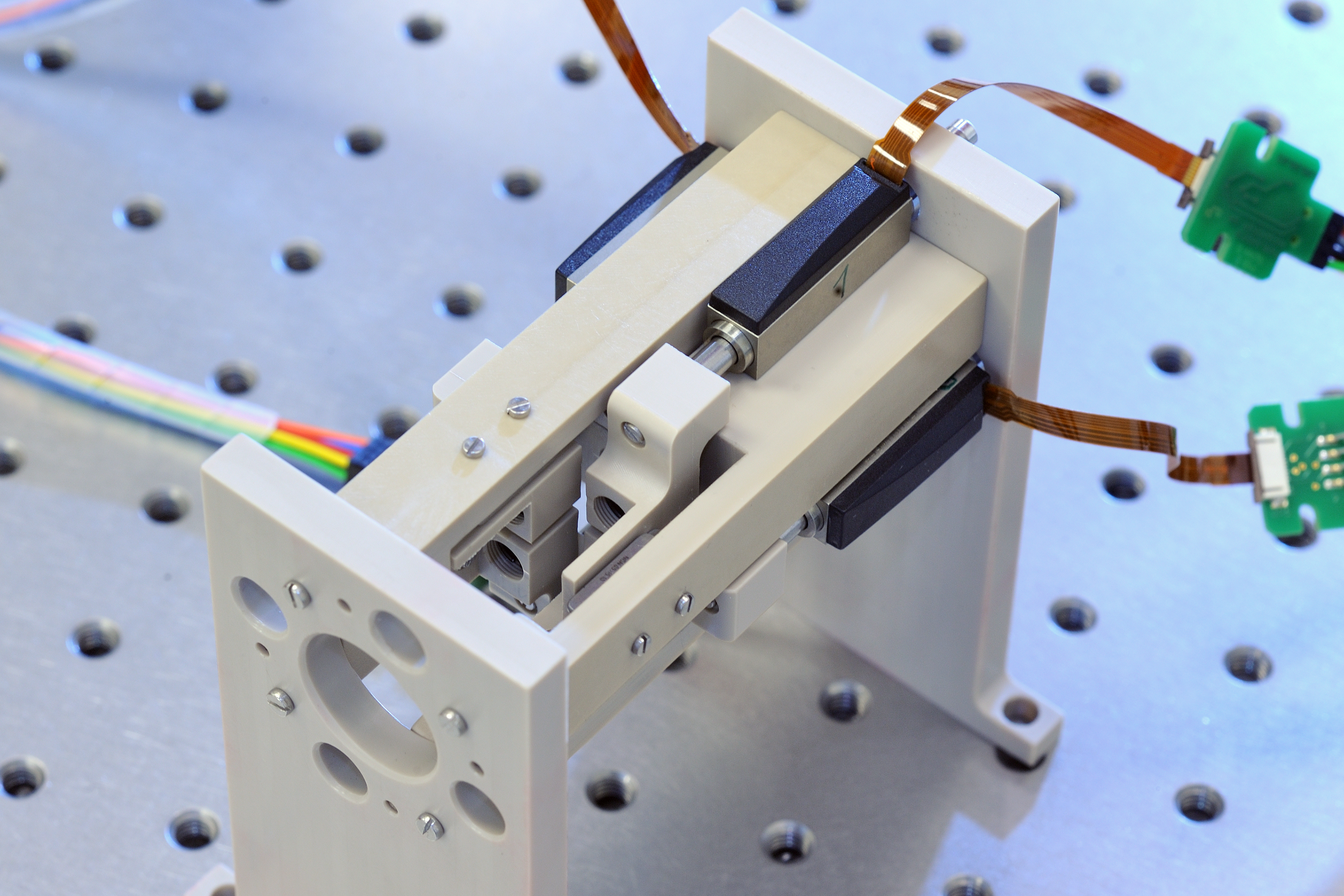
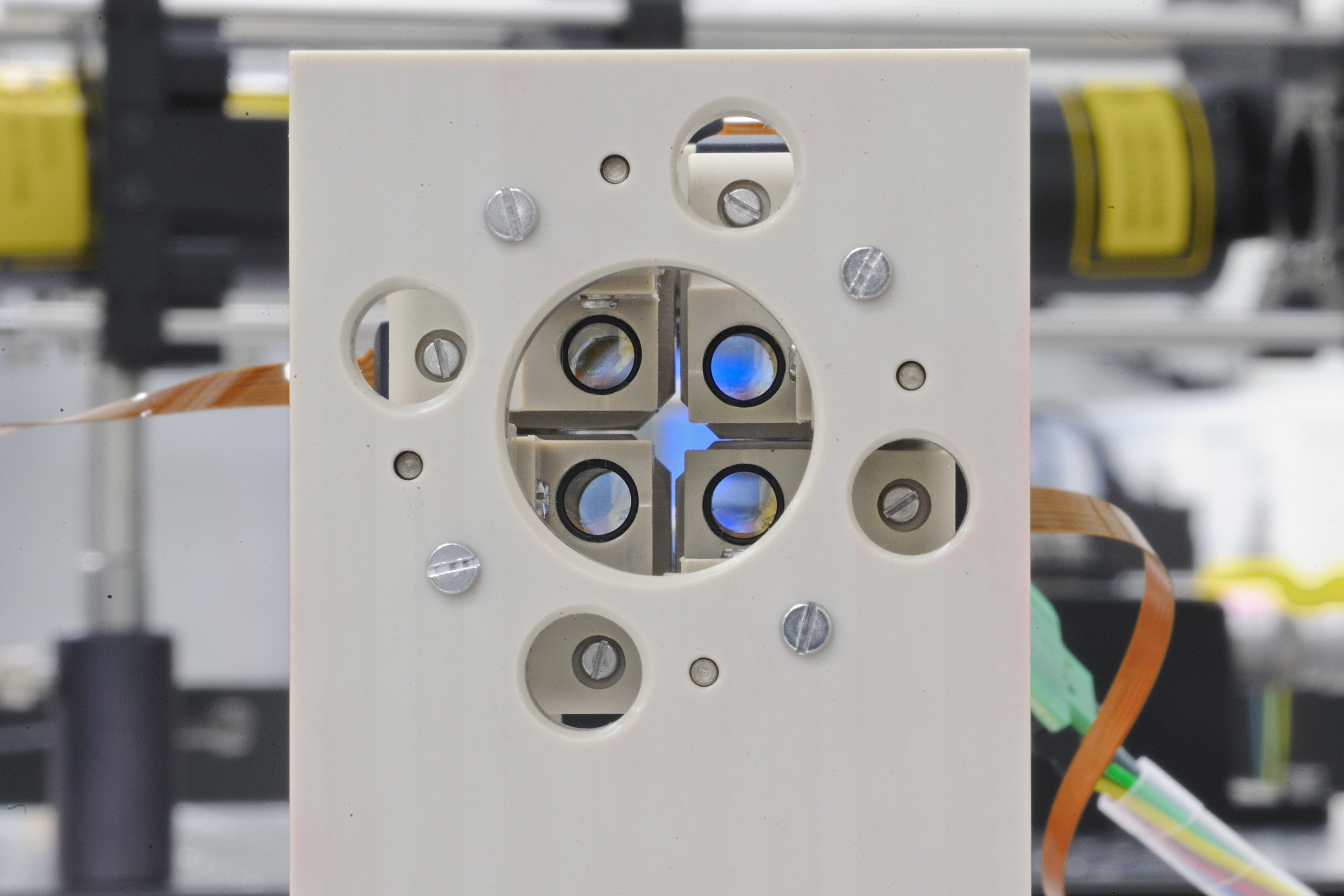
Extensive tests of the focus shifters showed, that the strong permanent and electromagnets within neighbouring linear stages heavily influence each other while moving. Thus, an updated design for the focus shifters was developed that increases the distance between the linear stages by arranging the stages in a star shape (cf. Figure 7). To avoid inductive effects from the strong and changing magnetic fields within the mechanical parts, the focus shifters were made out of polyether ether ketone (PEEK) – a readily machinable polymer (cf. Figure 8+9).

Figure 8: Top view of the focus shifters. To avoid inductive effects from the changing magnetic fields around the linear stages within e.g. aluminium , all parts were manufactured out of PEEK.
© Fraunhofer ILT, Aachen, Germany.
Figure 8: Top view of the focus shifters. To avoid inductive effects from the changing magnetic fields around the linear stages within e.g. aluminium , all parts were manufactured out of PEEK.
Figure: 9: Front view of the focus shifters.
© Fraunhofer ILT, Aachen, Germany.
Figure: 9: Front view of the focus shifters.

x-y-control unit

While the whole spot array can be laterally moved over the work piece with the laser scanner, the lateral movement of single beams relative to the spot array is not state of the art for multi-beam optics. The lateral position of a beam in the focal plane of the focusing lens is directly related to the lateral position of each beam between the first and the second relay module. Therefore, by laterally shifting a beam between the two relay modules, the beam is also laterally shifted in the focal plane of the focusing lens. The ratio between these lateral shifts is the ratio of the focal lengths of the f-theta lens and the second relay module.

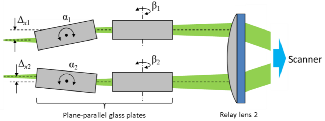
To realise such a lateral shift, a plane-parallel glass plate can be placed in the beam path (cf. Figure 10). Tilting the glass plate results in a lateral shift of the beam after the glass plate. The direction of a beam is not altered by a plane-parallel glass plate. If the glass plate can only be rotated around one axis, two glass plates per beam are required to adjust each beam in x- and y-direction.


Figure 10: Concept for an x-y-control unit. Rotatable plane parallel glass plates between the two relay lenses laterally shift the individual beams based on their rotation angle. This lateral shift is directly related to a lateral shift of the beams in the focal plane of the f-theta lens. The ratio of these two shifts is the ratio of the focal lengths of the f-theta lens and the second relay lens.
© Fraunhofer ILT, Aachen, Germany.
Figure 10: Concept for an x-y-control unit. Rotatable plane parallel glass plates between the two relay lenses laterally shift the individual beams based on their rotation angle. This lateral shift is directly related to a lateral shift of the beams in the focal plane of the f-theta lens. The ratio of these two shifts is the ratio of the focal lengths of the f-theta lens and the second relay lens.
Figure 11: Optical design for the x-y-control unit. Two glass plates are shown with their maximal tilt. The rotation axes of the two other plates are perpendicular to these of the former plates so a collision is not possible.
© Fraunhofer ILT, Aachen, Germany.
Figure 11: Optical design for the x-y-control unit. Two glass plates are shown with their maximal tilt. The rotation axes of the two other plates are perpendicular to these of the former plates so a collision is not possible.
Figure 12: 3D drawing of the mechanical design for the x-y-control unit.
© Fraunhofer ILT, Aachen, Germany.
Figure 12: 3D drawing of the mechanical design for the x-y-control unit.

The optical design of the x-y-control unit is shown in Figure 11. Fused silica glass plates with outer dimensions of 8x8x15 mm³ were chosen based on the remaining optical design and the restrictions from the mechanical design (see below). Note that in contrast to the concept in Figure 10, neighbouring plates are not rotated around the same axis but around perpendicular axes. This allow for larger glass plates and larger tilt angles without collisions between neighbouring plates. Additionally, this allows to position the motors for the rotation closer to each other making the system more compact. With the maximum rotation angle of the motors of ±11.4°, each beam can be laterally shifted in each direction by ±900 µm before the second relay lens and ±450 µm on the work piece.

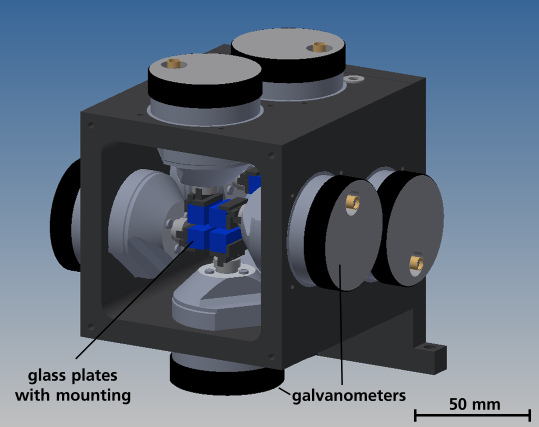
A 3D drawing of the mechanical design is shown in Figure 9. The glass plates are mounted on galvanometers to allow fast tilts synchronous with the laser scanner. The minimal distance between the two glass plates for a single beam (49 mm) is restricted by the size of the galvanometers.

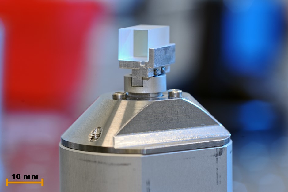
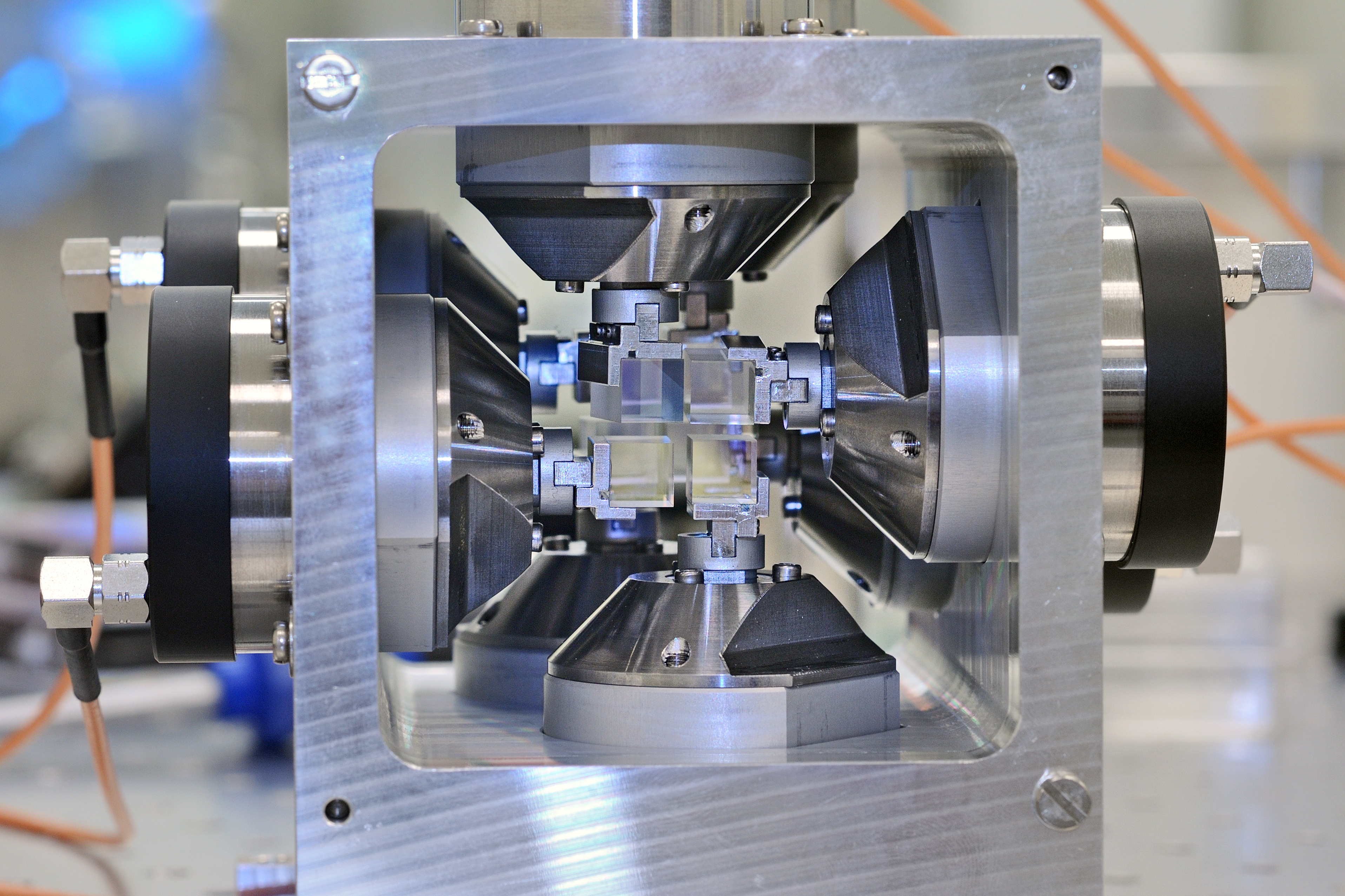
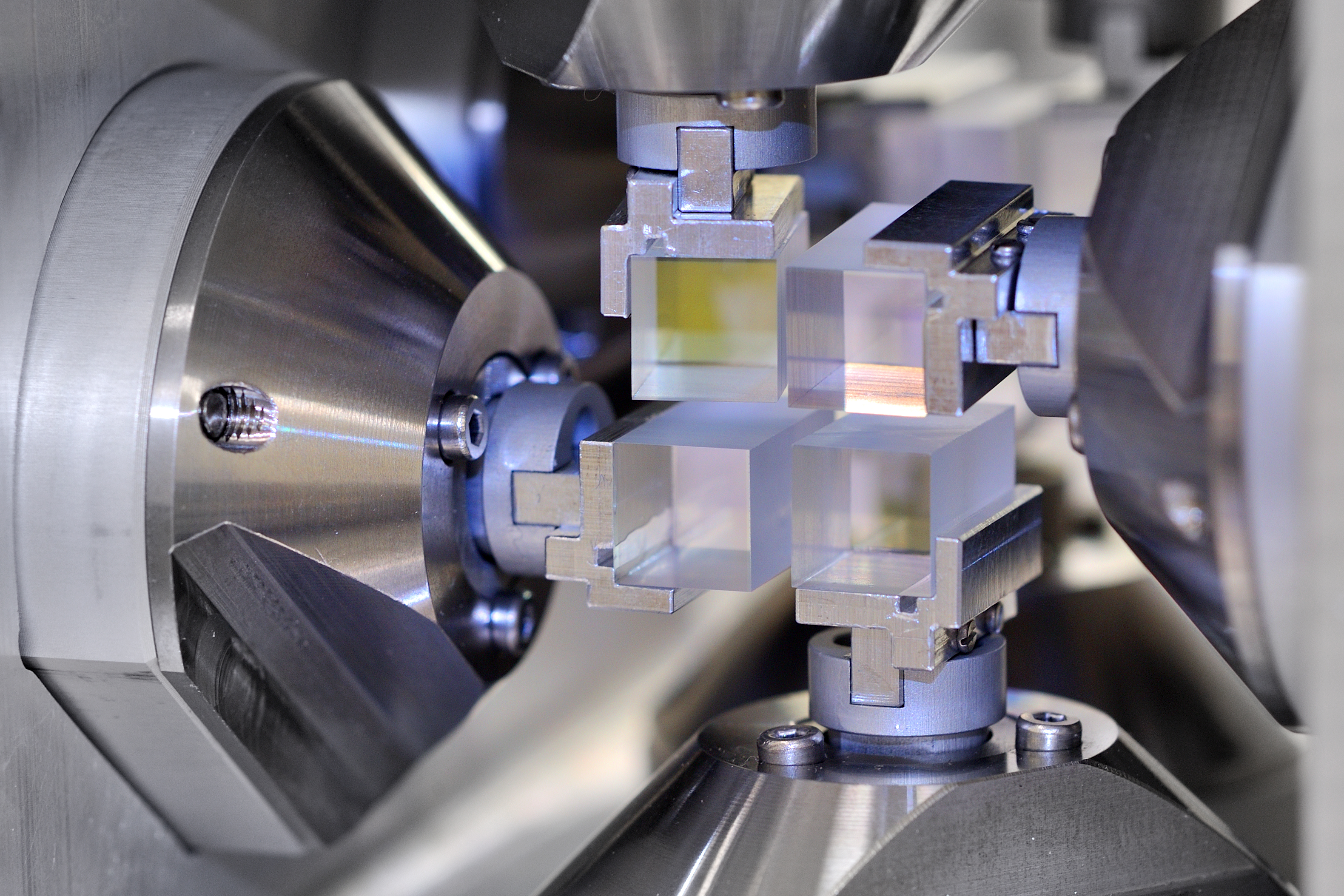
Figure 13 shows the mounting of a single glass plate on the galvanometer. The complete x-y-control unit is depicted in Figure 14 and a close up of the first row of glass plates is shown in Figure 15.

Figure 13: Individual glass plate on its mount and the corresponding galvanometer. The glass plate is made of AR-coated fused silica and has outer dimensions of 8x8x15 mm³.
© Fraunhofer ILT, Aachen, Germany.
Figure 13: Individual glass plate on its mount and the corresponding galvanometer. The glass plate is made of AR-coated fused silica and has outer dimensions of 8x8x15 mm³.
Figure 14: Front view of the assembled x-y-control unit
© Fraunhofer ILT, Aachen, Germany.
Figure 14: Front view of the assembled x-y-control unit
Figure 15: Close-up of the first row of glass plates. The rotation of each glass plate is mechanically limited by the galvanometers. As neighbouring plates rotate around different axes a collision of the plates is not possible.
© Fraunhofer ILT, Aachen, Germany.
Figure 15: Close-up of the first row of glass plates. The rotation of each glass plate is mechanically limited by the galvanometers. As neighbouring plates rotate around different axes a collision of the plates is not possible.

Complete optical design

Figure 16 shows the complete optical design for the multi-beam optics. The folding of the beam path with the two mirrors is only exemplarily. The actual folding is based on the available space in the optics head.

Figure 16: Side view of the optical design for the multi-beam system. The f-theta lens is a commercially available lens and shown here as the black box provided by the manufacturer. The laser scanner is not drawn here for better visibility. Note that the mirrors are only introduced to make the system more compact. The actual position of these mirrors is arbitrary. 4 beams are shown here (blue, red, yellow, green) but the blue and red beam are in front of the other two beams until the entrance aperture of the f-theta lens.
© Fraunhofer ILT, Aachen, Germany.
Figure 16: Side view of the optical design for the multi-beam system. The f-theta lens is a commercially available lens and shown here as the black box provided by the manufacturer. The laser scanner is not drawn here for better visibility. Note that the mirrors are only introduced to make the system more compact. The actual position of these mirrors is arbitrary. 4 beams are shown here (blue, red, yellow, green) but the blue and red beam are in front of the other two beams until the entrance aperture of the f-theta lens.

Assembly, implementation and characterisation

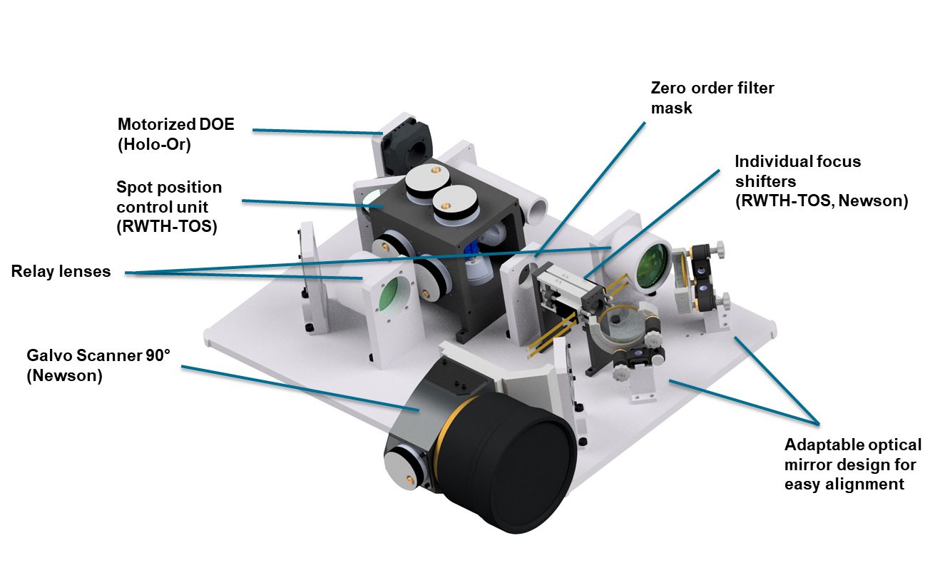
Figure 17: Multi-Beam optics in the lab
© Fraunhofer ILT, Aachen, Germany.
Figure 17: Multi-Beam optics in the lab

The mechanical design for the Multi-Beam optics was developed and manufactured. The optics was successfully assembled and characterized and meet the requirements for laser structuring. Thus the Multi-Beam optics was integrated in the 5-axis laser machine tool to process parts of the end-users. 3D capability could be demonstrated on simple geometries. The optics can be used as a prototype for product development.

Figure 18: Closer look into the Multi-Beam optics
© Fraunhofer ILT, Aachen, Germany.
Figure 18: Closer look into the Multi-Beam optics

Beam-Shaping Optics

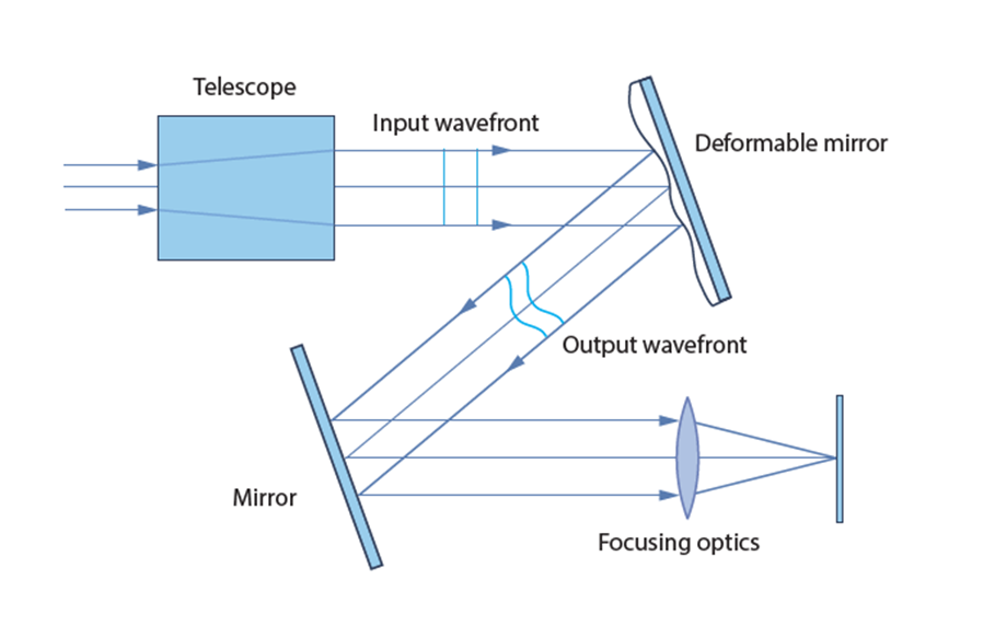
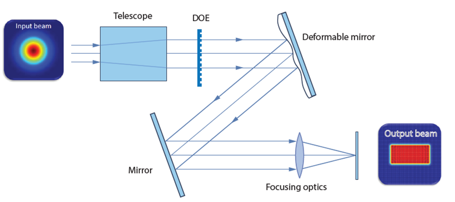
Figure 1 shows exemplary target intensity distributions for the beam-shaping optics. Based on these and the remaining application requirements, an initial concept for the beam-shaping processing system was developed (cf. Figure 2): A collimated laser beam with known intensity distribution (ideally a Gaussian beam) is fed into the system. A telescope is then used to optimally illuminate the deformable mirror. Any deviation from a flat surface of the deformable mirror imprints a phase change on the initially flat wavefront of the laser beam. An undistorted wavefront would lead to a mainly diffraction limited Gaussian spot in the focal plane of a focussing lens (usually an F-Theta lens). A distorted wavefront will lead to a different beam shape based on the phase distortion. The goal is to identify the phase change that will lead to the desired intensity distribution. There are infinite solutions for a given intensity distribution as the intensity of a beam carries less information than its wavefront or phase. The challenge is to find an efficient optical design that requires the least phase change.

Figure 1: Exemplary intensity distributions for the beam-shaping system. Left: rectangular tophat with triangular cutoff for laser polishing. Right: Rectangular intensity distribution with gradient along the long axis for thin-film processing. Ideally, the form of the cutoff (left) and the gradient (right) should be customizable.
© Fraunhofer ILT, Aachen, Germany.
Figure 1: Exemplary intensity distributions for the beam-shaping system. Left: rectangular tophat with triangular cutoff for laser polishing. Right: Rectangular intensity distribution with gradient along the long axis for thin-film processing. Ideally, the form of the cutoff (left) and the gradient (right) should be customizable.

While, in principle, it is possible to create arbitrary beam shapes with this concept one has to consider the diffraction limit and the limitations of the deformable mirror regarding its surface shape (e.g. amplitude of height changes and spatial frequency). Diffraction effects will always smear out any sharp edges in the spot thus limiting the edge steepness. And as the mirror consists of a continuous membrane or face plate with a limited number of actuators, steep gradients and sharp gradient changes in the surface shape (and therefore imprinted phase) cannot be realised.

Figure 2: Initial concept for the beam-shaping system. A collimated laser beam is expanded to optimally illuminate the deformable mirror. The deformable mirror then imprints a phase change onto the beam based on the current shape of the mirror. Based on the phase change, the desired intensity distribution is then realized in the focal plane of a focusing optic. The second mirror is only shown here to visualize the system in a more compact way.
© Fraunhofer ILT, Aachen, Germany.
Figure 2: Initial concept for the beam-shaping system. A collimated laser beam is expanded to optimally illuminate the deformable mirror. The deformable mirror then imprints a phase change onto the beam based on the current shape of the mirror. Based on the phase change, the desired intensity distribution is then realized in the focal plane of a focusing optic. The second mirror is only shown here to visualize the system in a more compact way.

Feasibility study of initial concept

The concept as seen in Figure 2 was simulated within a commercially available ray-tracing software. Analytic models for the deformable mirrors were developed and integrated into the ray-tracing software. This integration is available for free from www.okotech.com/zemax-dm-uds. Additionally, a software tool was developed that allows to calculate the required energy redistribution from a Gaussian input beam to achieve the target intensity distribution (so called beam mapping).

Firstly, the target intensity distributions shown in Figure 1 were approximated with simple rectangular flat-tops (i.e. uniform intensity distribution over the whole rectangle) with the same outer dimensions. Best results were seen with a 79 channel, 50 mm diameter piezoelectric deformable mirror (PDM).

Figure 3: Simulated beam shaping results with a 79 ch, 50 mm diameter PDM. a): 400 µm square tophat,  b): 800 µm x 400 µm tophat, c): 1000 µm x 250 µm tophat
© Fraunhofer ILT, Aachen, Germany.
Figure 3: Simulated beam shaping results with a 79 ch, 50 mm diameter PDM. a): 400 µm square tophat, b): 800 µm x 400 µm tophat, c): 1000 µm x 250 µm tophat

The beam size on the mirror was found to be a crucial parameter for the quality of the realised intensity distributions. If the beam is too small, too few of the actuators of the mirror are effectively used for beam shaping. If the beam is too large, the lowered actuator density at the edge of the mirror and reduces the beam shaping capabilities and diffraction effects heavily impact the result.

As seen in Figure 3, the PDM is well suited to generate almost diffraction limited rectangular tophats of various sizes and aspect ratios. The orientation of the rectangles is arbitrary for the beam shaping with the deformable mirror but for consistency and better comparability, all shown rectangles are orientated in the same way. Note that shaping a 1500 µm x 400 µm rectangle (target distribution for laser polishing) in the focal plane of the focusing optics is not possible with this concept as shown in Figure 5 a). The required amplitude of the phase change is too large for the PDM to realise. As only the total size of the intensity distribution and not the aspect ratio is the problem (as a 4:1 aspect ratio is demonstrated to work in Figure 3 c)) one can solve this drawback by adding another telescope in front of the focusing lens (cf. sec. 1.4). Another solution is to not work within the focal plane of the focusing optics but in front of it (or behind it). As the undistorted spot is already larger there, less phase change is required to achieve the target intensity distribution (cf. Figure 5 b)). However, the realisation of a 5 mm x 1 mm rectangle (target distribution for thin film processing) is not possible with the initial concept. And while shaping a 1500 µm x 400 µm rectangular tophat is possible with this concept, the PDM is not able to produce the desired cutoff as shown in Figure 1 (cf. Figure 5 c)). Thus, an alternative concept had to be developed.

Note that most simulations in the feasibility studies were performed with a focal length of the F-Theta lens of 450 mm as this is a typical focal length already used in laser polishing applications at FHG-ILT. Such a long focal length also allows for better beam shaping results as the required gradient of the deformable mirror surface for a given intensity distribution is inversely proportional to the focal length of the objective.

Figure 5: Simulated beam shaping results with OKOTech 79 ch, 50 mm diameter PDM. a): attempted 1500 µm x 400 µm tophat in focal plane of the focusing optics (450 mm focal length), b): 1500 µm x 400 µm tophat 20 mm in front of the focal plane of the focusing optics (450 mm focal length), c) attempted 1500 µm x 400 µm tophat with triangular cutoff 20 mm in front of the focal plane of the focusing optics (450 mm focal length).
© Fraunhofer ILT, Aachen, Germany.
Figure 5: Simulated beam shaping results with OKOTech 79 ch, 50 mm diameter PDM. a): attempted 1500 µm x 400 µm tophat in focal plane of the focusing optics (450 mm focal length), b): 1500 µm x 400 µm tophat 20 mm in front of the focal plane of the focusing optics (450 mm focal length), c) attempted 1500 µm x 400 µm tophat with triangular cutoff 20 mm in front of the focal plane of the focusing optics (450 mm focal length).

Feasibility study of alternative concepts

The initial concept was modified in an attempt to realise the target intensity distributions with the deformable mirror.  As already addressed, a second telescope behind the deformable mirror allows to produce expanded intensity distributions but also leads to less sharp edges due to more diffraction. But even then, the characteristics of the available PDM do not allow to produce a 5 mm x 1 mm tophat. The second telescope also does not improve the capability to create the cutoff within the tophat.

A concept with two deformable mirrors has been investigated as well. While this slightly improves the overall performance of the system, the required phase gradient to produce the cutoff is still too steep for the PDMs to realize.

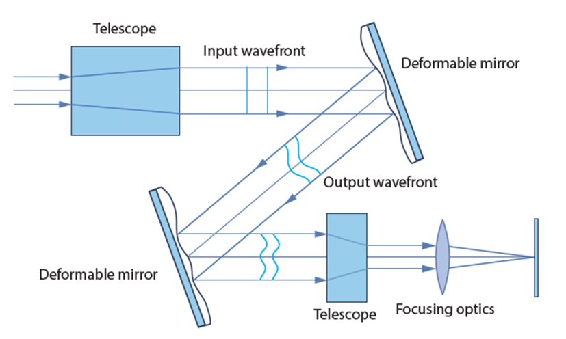
A combined concept with two PDMs and a second telescope was investigated as well (cf. Figure 6) but the above mentioned problems still prevail.


Figure 6: Alternative concept for the beam-shaping system. Compared to the initial concept, a second deformable mirror and a second telescope in front of the focusing optics were added to improve the beam-shaping capabilities of the system. The concept of only adding a second deformable mirror or a second telescope to the initial concept were investigated priorly but are not shown here separately.
© Fraunhofer ILT, Aachen, Germany.
Figure 6: Alternative concept for the beam-shaping system. Compared to the initial concept, a second deformable mirror and a second telescope in front of the focusing optics were added to improve the beam-shaping capabilities of the system. The concept of only adding a second deformable mirror or a second telescope to the initial concept were investigated priorly but are not shown here separately.

Final Concept

As the deformable mirrors are not able to achieve the target intensity distributions for ultraSURFACE, a static beam shaping device has to be used. Diffractive optical elements (DOEs) are used that will produce the desired intensity distributions (cf. Figure 2) in the focal plane of the chosen focusing optics (cf. Figure 7). Dynamic beam shaping with the PDM is still required within ultraSURFACE as the distortion of the pre-shaped intensity distribution by the focusing optics for large scanning angles and on tilted surface still needs to be compensated.

As the orientation of the intensity distribution on the work piece should be arbitrary, it is necessary to rotate the DOE with a hollow shaft motor. While the PDM is able to produce intensity distributions with arbitrary orientations itself, it cannot rotate the pre-shaped distributions that were chosen for the ultraSURFACE project.

Figure 7: Final concept for the beam-shaping system. A DOE imprints the phase that produces the target intensity distribution on the focal plane of a focusing optic. The deformable mirror can then modify that phase for further adjustments of the intensity distribution e.g. to compensate for a tilted surface in the target plane.
© Fraunhofer ILT, Aachen, Germany.
Figure 7: Final concept for the beam-shaping system. A DOE imprints the phase that produces the target intensity distribution on the focal plane of a focusing optic. The deformable mirror can then modify that phase for further adjustments of the intensity distribution e.g. to compensate for a tilted surface in the target plane.

Assembly, implementation and characterisation

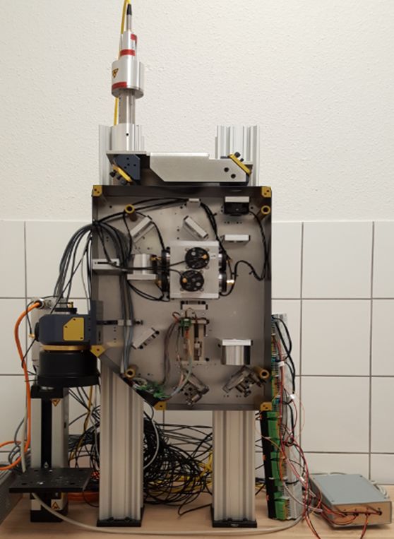
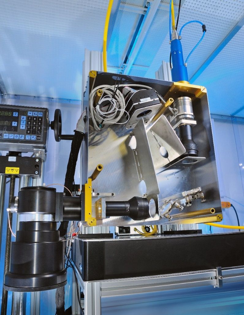
Figure 8: Beam-Shaping optics in the lab
© Fraunhofer ILT, Aachen, Germany.
Figure 8: Beam-Shaping optics in the lab

The mechanical design for the Beam-Shaping optics was developed and manufactured. The optics was successfully assembled and characterized. Although multiple optimization steps the optical performance of the Beam-Shaping optics does not meet the requirements for dynamic beam shaping for the two laser processes laser polishing and laser thin film processing. Thus further optimization and a closed-loop control of the deformable mirror are necessary.

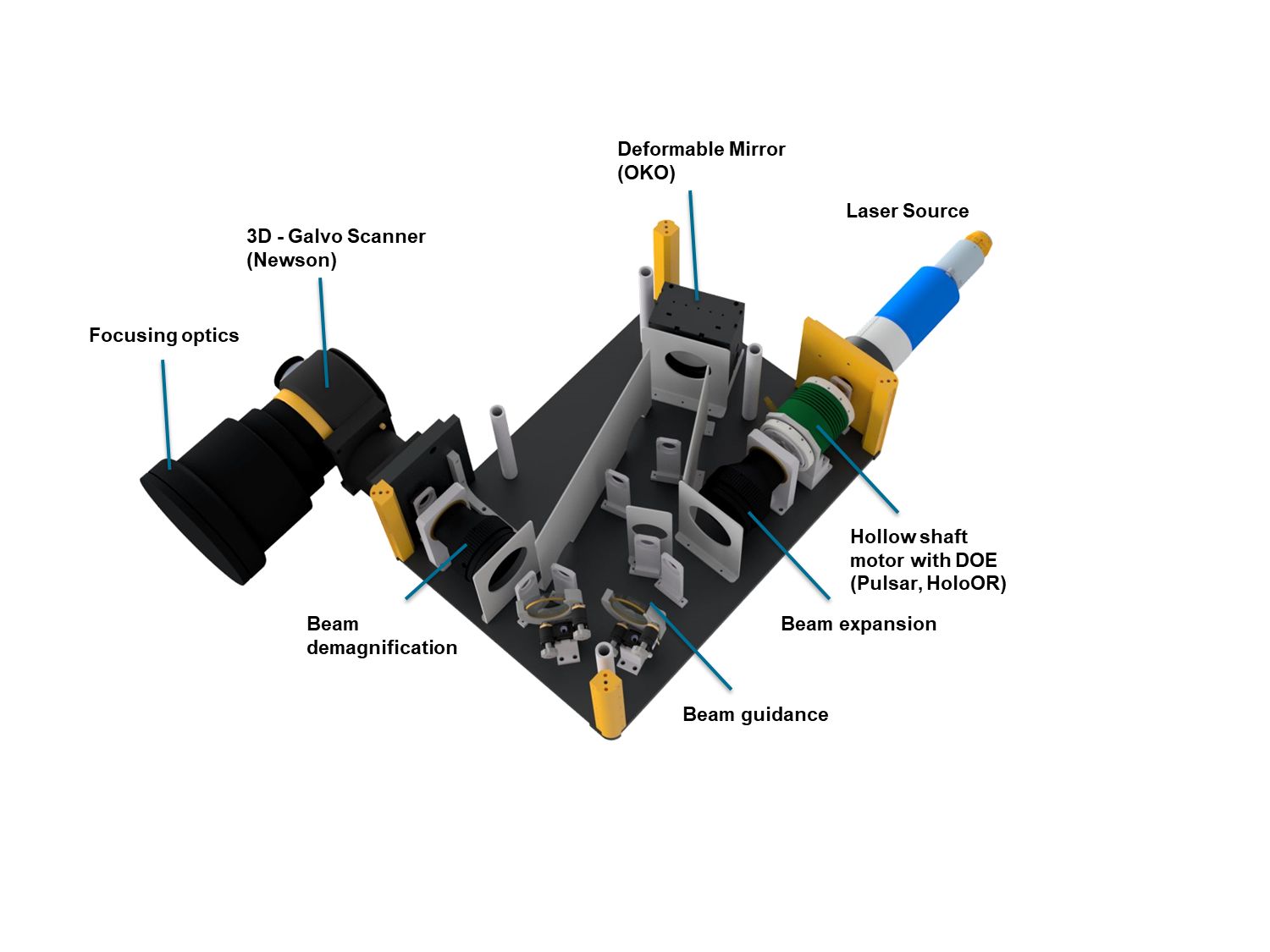
Figure 9: Closer look into the Beam-Shaping optics
© Fraunhofer ILT, Aachen, Germany.
Figure 9: Closer look into the Beam-Shaping optics

Machine Integration

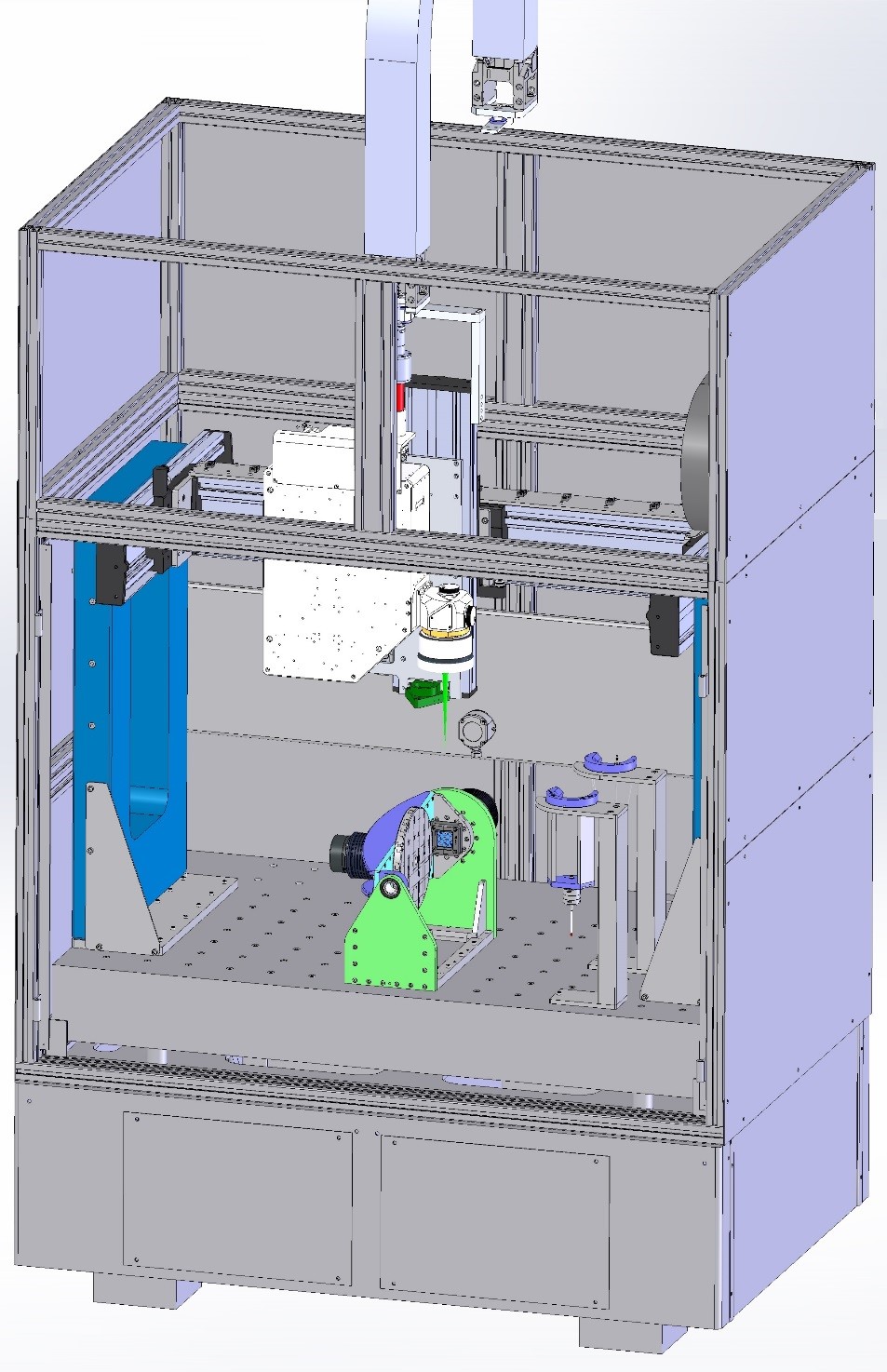
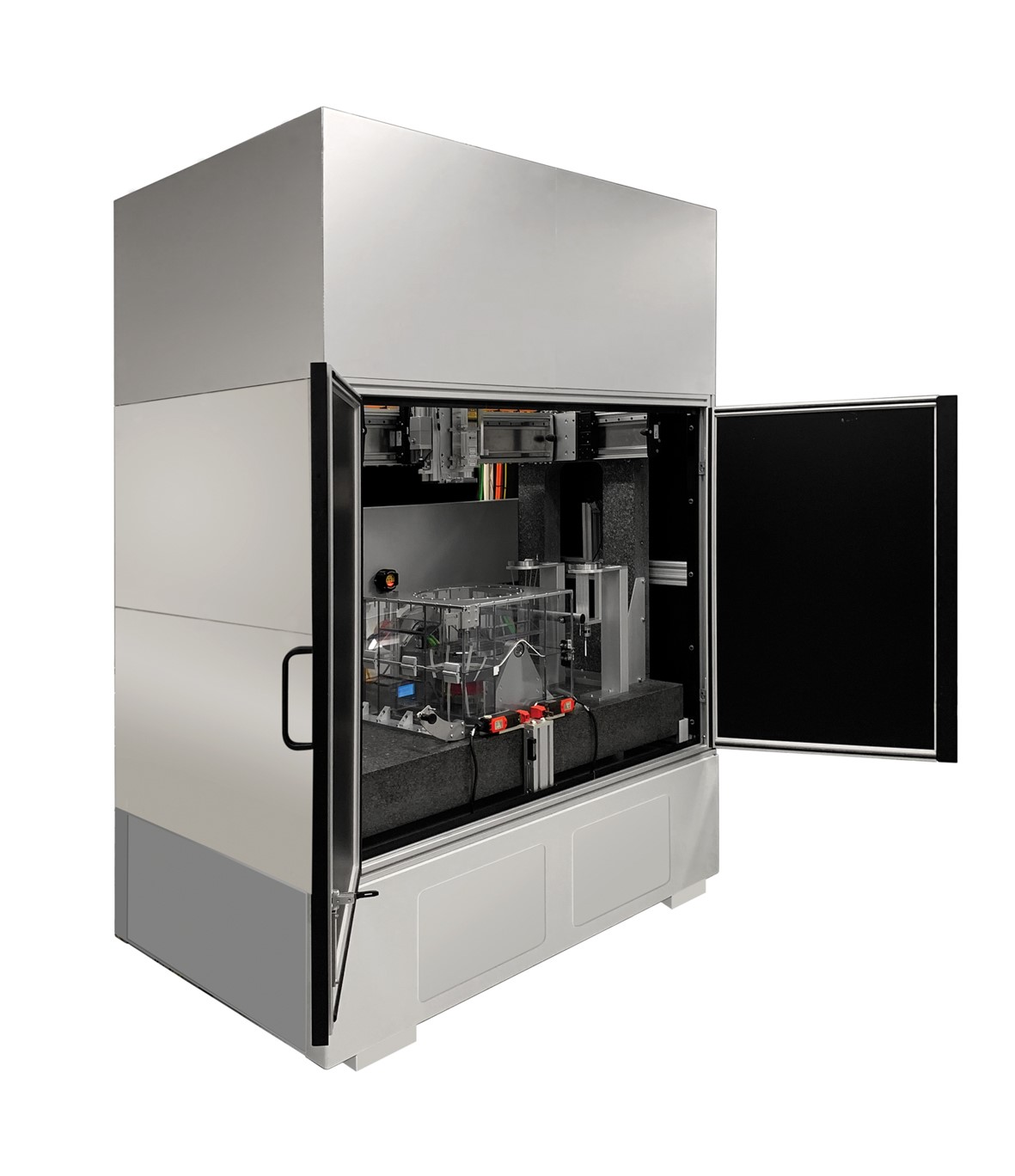
Figure 1: Platform design
© Fraunhofer ILT, Aachen, Germany.
Figure 1: Platform design

The machine developed at Unitechnologies SA is now equipped with the Multi Beam Optics developed during the project. The mentioned equipment went through the traditional development stages to finally reach its maturity as an operational machine.

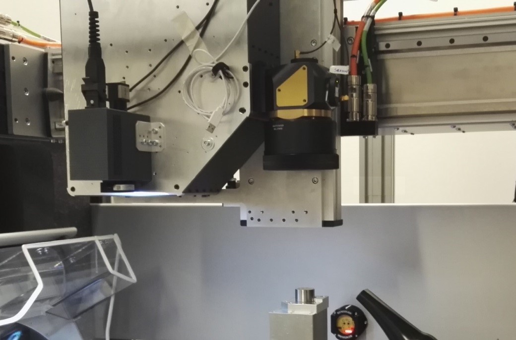
Figure 2: Implemented platform
© Fraunhofer ILT, Aachen, Germany.
Figure 2: Implemented platform

The main platform features are the measurement of the real part with a tactile probe (referencing on the work piece) and the continuous five axis processing.

Among other characteristics the implemented software & process chain allows to "simulate" and generate the iso programs to be executed on the platform.

Figure 3: Process commissioning
© Fraunhofer ILT, Aachen, Germany.
Figure 3: Process commissioning
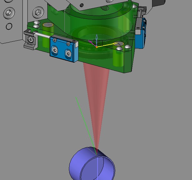
Figure 4: "Simulated" trajectory
© Fraunhofer ILT, Aachen, Germany.
Figure 4: "Simulated" trajectory
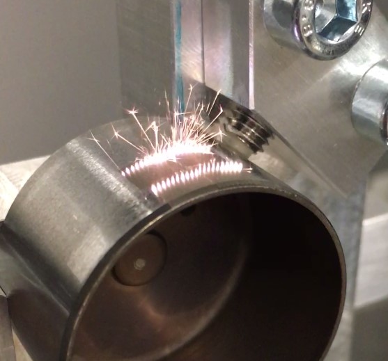
Figure 5: Detail of the real trajectory & process
© Fraunhofer ILT, Aachen, Germany.
Figure 5: Detail of the real trajectory & process

First commissioning tests allowed to verify the functions of the implemented ultrasurface platform and optics.

First Application Tests with the developed MultiBeam Optics

The video shows first application tests for laser structuring with the developed MultiBeam optics, which were integrated into a machine tool at Unitechnologies.

Application testing and evaluation of economic efficiency

With the integrated Multi-Beam optics different parts of the end-users could successfully be laser structured. Different application tests on the laser structured parts were performed and showed promising results. A reduction of the processing time by a factor of 3 was achieved using the Multi-Beam optics. For one concrete case (which cannot be presented here due to confidentiality) a cost reduction of 58 % results.